The challenge
Turn a model-based design for a sub-kilowatt Hall thruster into real hardware that can be fired and measured.
Electric propulsion · PEPPR · In progress
I’m working with PEPPR to manufacture and integrate HET-01, a sub-kilowatt electric thruster. The vacuum test setup is ready and the magnets are characterized. The first full firing is next.
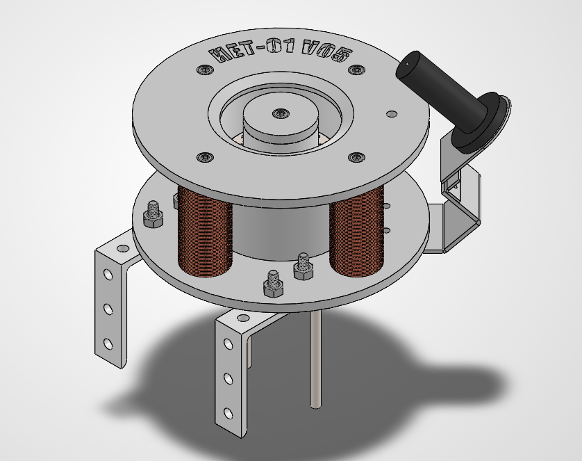
The challenge
Turn a model-based design for a sub-kilowatt Hall thruster into real hardware that can be fired and measured.
What I’m doing
Manufacturing and integrating the thruster hardware, alongside a team that prepared the vacuum test setup and characterized the magnets.
Where it stands
Test-ready: the vacuum chamber is prepared and the magnetic system is characterized. Integration and the first full firing are next.
Power, voltage, and thrust are targets from the design model, not measured results.
A Hall-effect thruster is an electric rocket engine used to move and steer satellites in space. Instead of burning fuel, it uses electricity to turn a gas into plasma and fire it out at very high speed. The push is gentle, about the weight of a few paper clips, but it’s extremely fuel-efficient and can run for thousands of hours.
Krypton flows in through the anode at the back of a ring-shaped channel.
Electrons from the cathode get trapped by the magnetic field and knock electrons off the krypton atoms, turning them into ions.
An electric field fires the ions out of the channel at about 15 km/s (design value), pushing the spacecraft the other way.
Sized the channel and power level with a Hall-thruster scaling model.
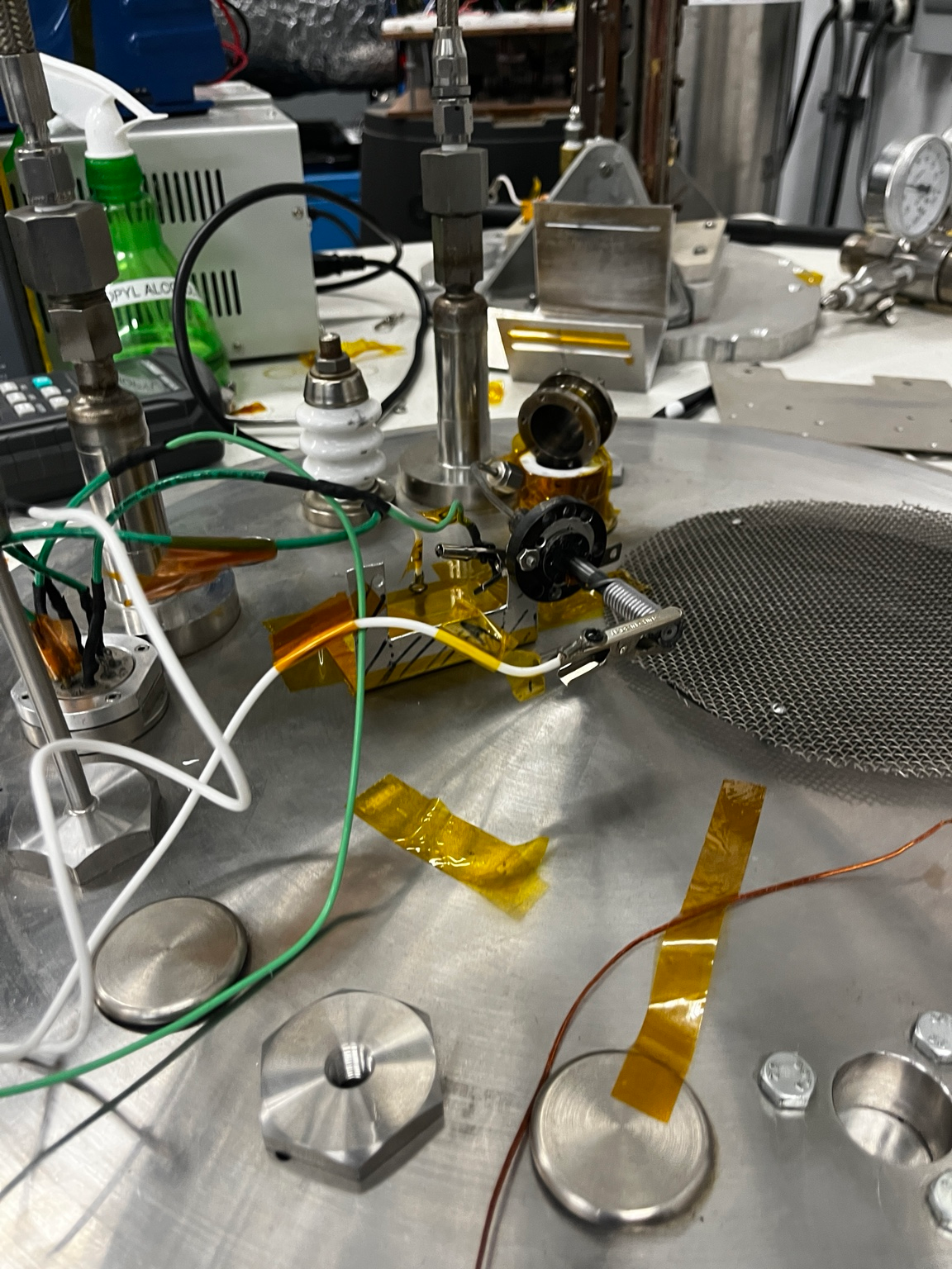
Got the vacuum chamber and test setup ready for firing.
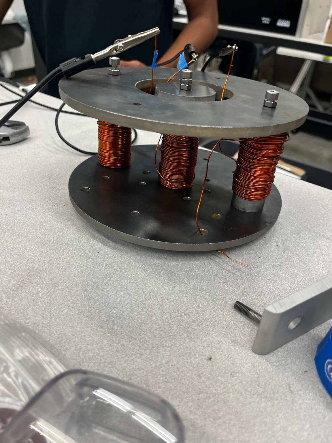
Measured the magnetic system before full operation.
Manufacturing and integrating the hardware for the first full-thruster test.
I am working with PEPPR to manufacture and integrate a sub-kilowatt Hall-effect thruster. The full design has not yet fired, but the team has prepared the vacuum chamber and test setup and characterized the magnet system ahead of full-thruster testing.
Build hardware, verify subsystems, then test the integrated thruster
Scaling-law model used to size the initial concept
The initial geometry uses a sub-kilowatt Hall-thruster scaling approach: a 59 mm mean channel diameter, 14 mm channel width, and 25 mm channel length. These are model-based design inputs, not measured performance results.
From a credible design model to an operating propulsion system
The work connects propulsion sizing, magnetic-field geometry, component manufacturing, and vacuum-facility preparation. Full-thruster operation will validate how the manufactured system performs as an integrated assembly.