PVC Knee Scooter
Mechanical design-build | ME 328 | Cal Poly San Luis Obispo
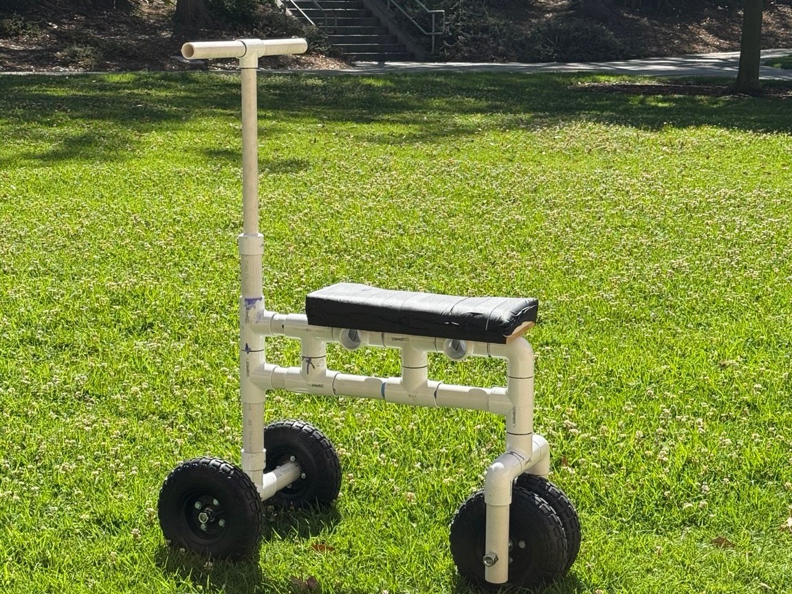
Working with Daniel Mendes, Chananeth Manava, and Hong Dang, I designed, analyzed, built, and tested a low-cost knee scooter from Schedule 40 PVC. The project moved from anthropometric requirements and hand calculations through two FEA iterations, physical fabrication, and test-based validation.
Design requirements and architecture
A stable, low-cost alternative to crutches
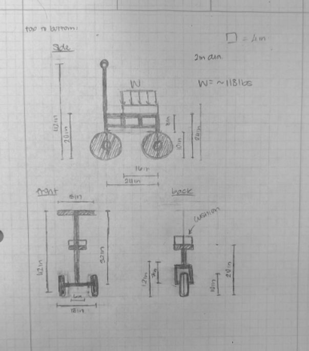
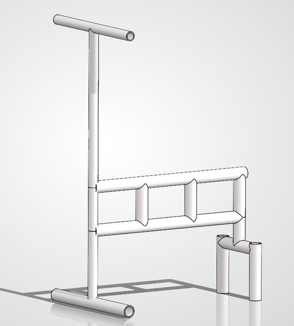
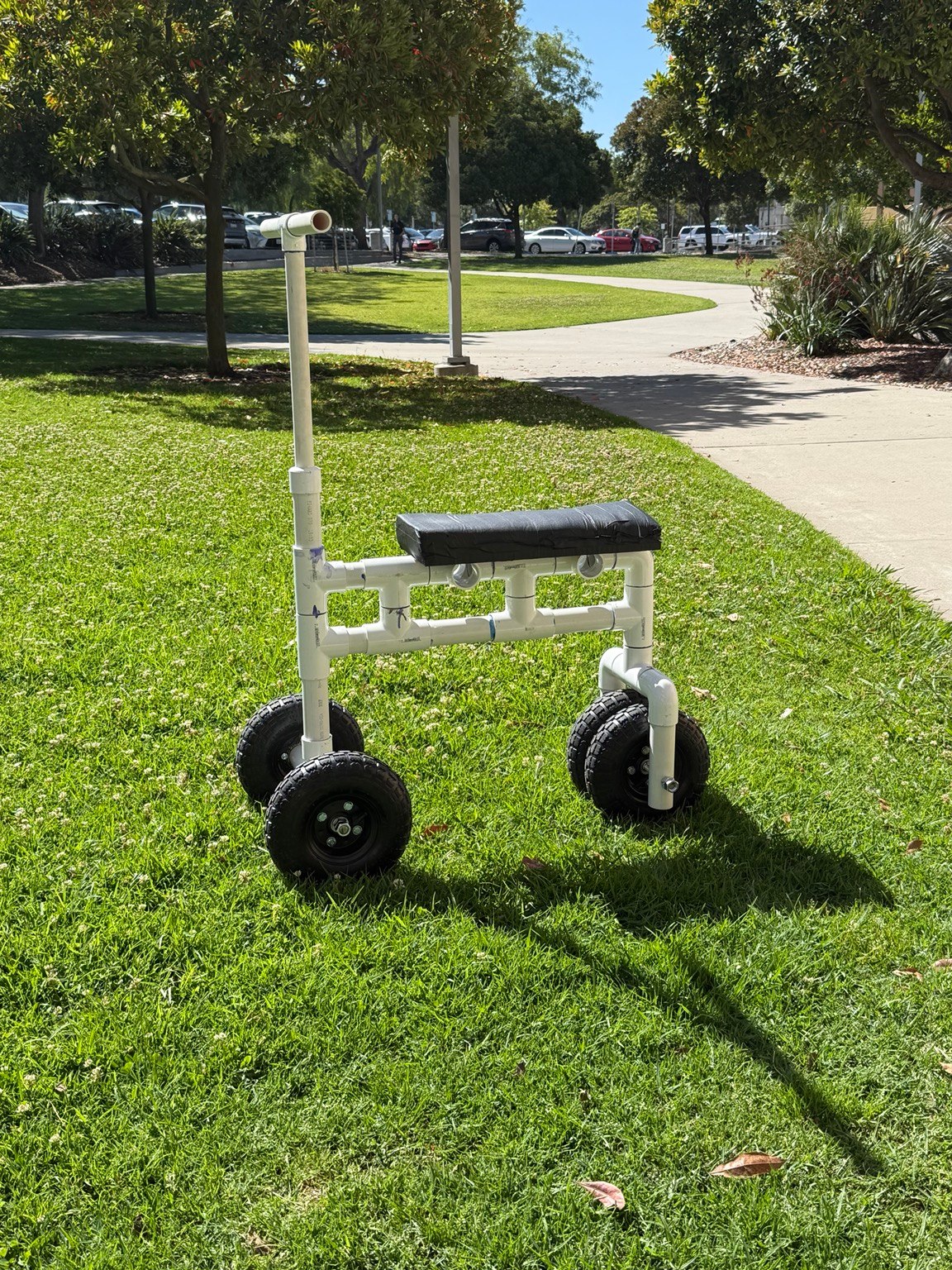
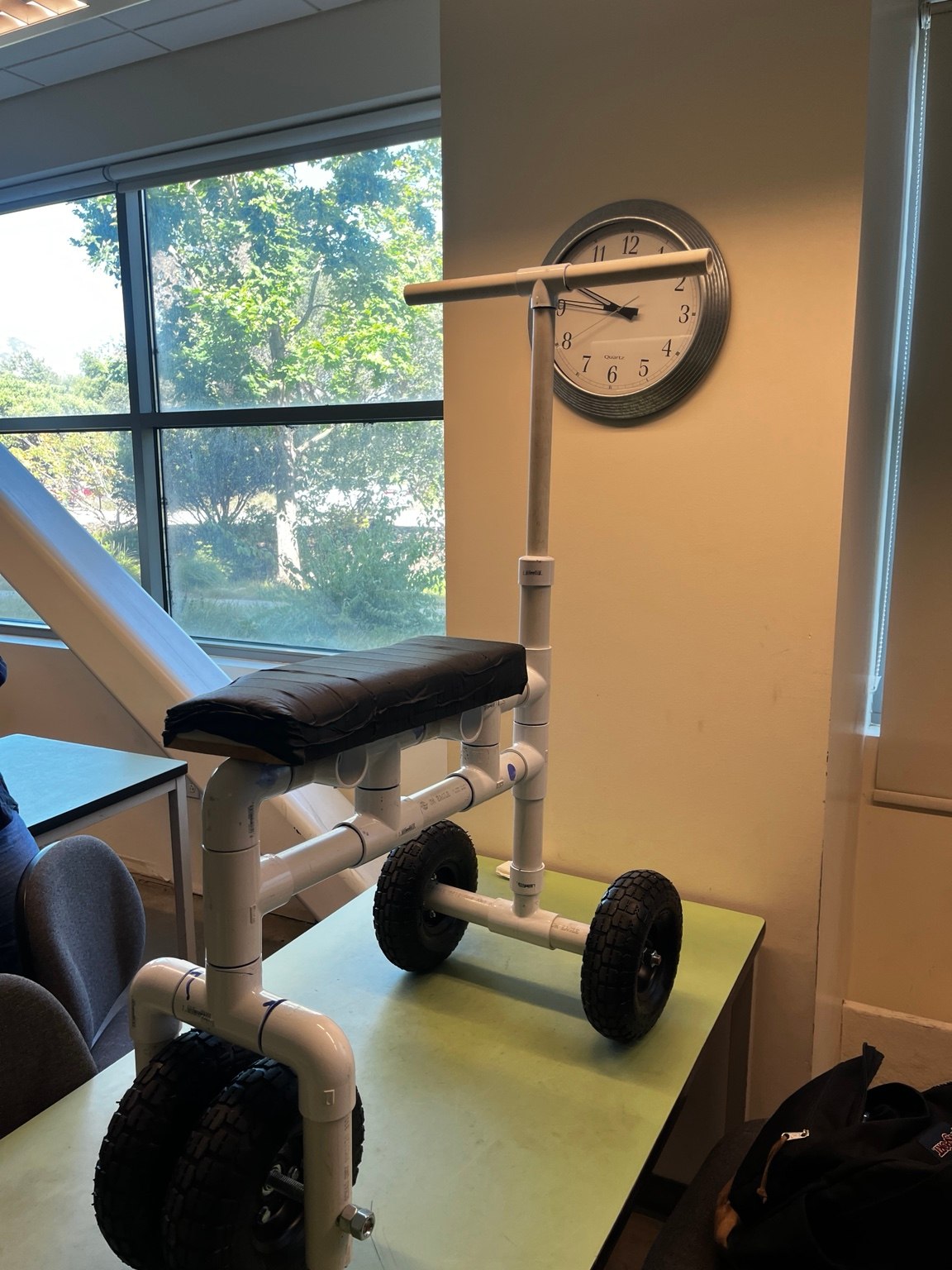
The design supports an injured leg on a padded platform while the rider pushes with their healthy leg and steers through a rotating front column. A wide front track improves lateral stability, while a compact rear wheel assembly leaves clearance for the rider's pushing leg.
The final configuration uses a rectangular, truss-like PVC frame to distribute knee loads and limit bending. Cross fittings support the knee platform, and bored end caps create a pivot for the steering column. The geometry was sized from anthropometric measurements rather than selected by eye.
Load cases and hand calculations
Bounding normal use and foreseeable misuse
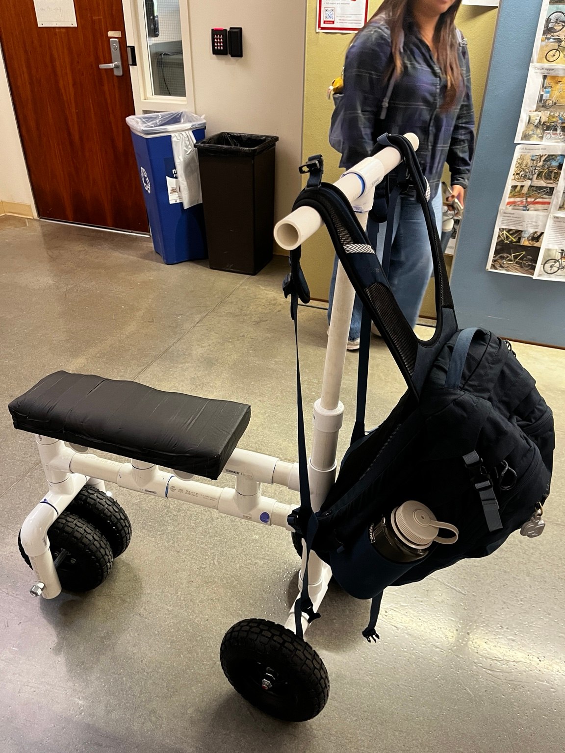
I evaluated three scenarios: the rider's weight on the knee platform, the rider plus a backpack, and an abuse case with a 10 lb bag hanging from each handlebar end. The heavier knee-platform case governed the frame calculation, while the bag load isolated bending and deflection in the handlebars.
With a safety factor of two applied, the knee support was checked under a 246 lb design load. Simplified beam theory predicted 0.080 in of platform deflection. For the handlebar case, a 90 lb-in bending moment produced an estimated 262 psi maximum stress and 0.013 in tip deflection.
| Load case | Purpose | Applied condition | Primary check |
|---|---|---|---|
| Normal use | Daily operation | User load on knee pad | Frame stiffness |
| User + backpack | Maximum expected use | 246 lb factored design load | Knee-platform deflection |
| Handlebar abuse | Foreseeable misuse | 10 lb at each handlebar end | Steering-column bending |
FEA-driven optimization
Reducing excess strength without sacrificing safety
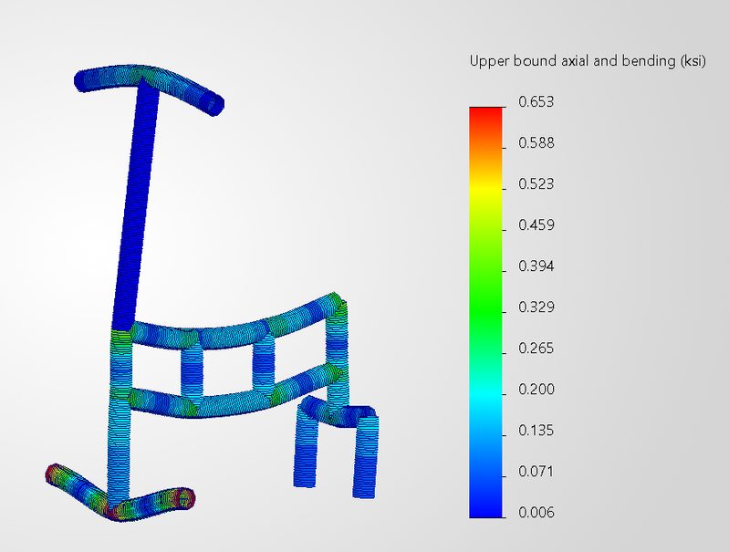
The first solid-element model used 1.5 in PVC throughout, fixed the four wheel-mount locations, and applied 150 lb over the knee-support area plus 10 lb at each handlebar end. Its maximum stress was approximately 0.65 ksi, corresponding to a safety factor near 10 against the reported 6-8 ksi ultimate strength of PVC.
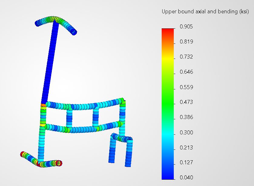
Because the first design carried more margin than necessary, the steering column and handlebars were reduced to 1 in PVC. The final model predicted approximately 0.905 ksi maximum stress and 0.149 in maximum displacement, with the most critical region located where the steering column meets the front crossbar.
Fabrication and prototype testing
Turning a simulation model into a working mobility device
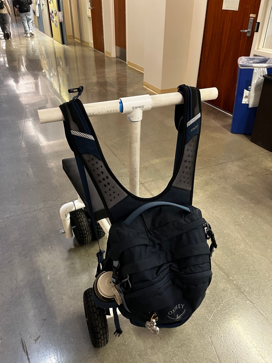
The frame was dry-fit first so dimensions, alignment, and wheel placement could be corrected before permanent bonding. After verification, the structural joints were primed and glued, the steering column was left free to rotate, threaded rod formed the wheel axles, and foam over a wood platform created the knee support.
Testing covered static load capacity, handlebar loading, structural integrity, turning, and rider fit. The unglued frame supported roughly twice the intended weight with little visible deflection. A later 20 lb handlebar load produced about 0.0625 in of measured deflection, and no measurable main-frame deflection was observed at the intended user load.
Validation and next iteration
Comparing prediction, observation, and user feedback
Both FEA and physical testing identified the handlebar ends as the most flexible region. The measured 0.0625 in displacement was less than half of the 0.149 in prediction, so the model was conservative while still capturing the correct deformation pattern. The extra stiffness likely came from glued fittings and local reinforcement that were simplified in the simulation.
Physical testing also exposed issues the structural model could not: dry-fit joints twisted during sharp turns, fitting stack-up made the scooter too tall for the original user, and the steering-column connection remained the main source of wobble. A future version should add adjustable handlebar and knee-platform heights, reinforce the steering pivot, use aluminum tubing for durability, and include a hand-operated brake.