The problem
A B-2’s complex shape has no simple formula for its inertia. The only way to know it is to measure it, and to trust the measurement.
Experimental dynamics · Cal Poly San Luis Obispo
Engineers need to know how an aircraft’s mass is spread out to predict how it handles. With a teammate, I measured a B-2 Spirit model’s roll and yaw inertia, after first proving our test methods on a board we could check by hand.
The problem
A B-2’s complex shape has no simple formula for its inertia. The only way to know it is to measure it, and to trust the measurement.
What I did
Proved two test methods on a wood board with a known answer, then used the more reliable method on the B-2 model.
The result
Board results landed as close as 3.56% to theory. I delivered roll and yaw values for the B-2 and pinpointed how to shrink the biggest source of error.
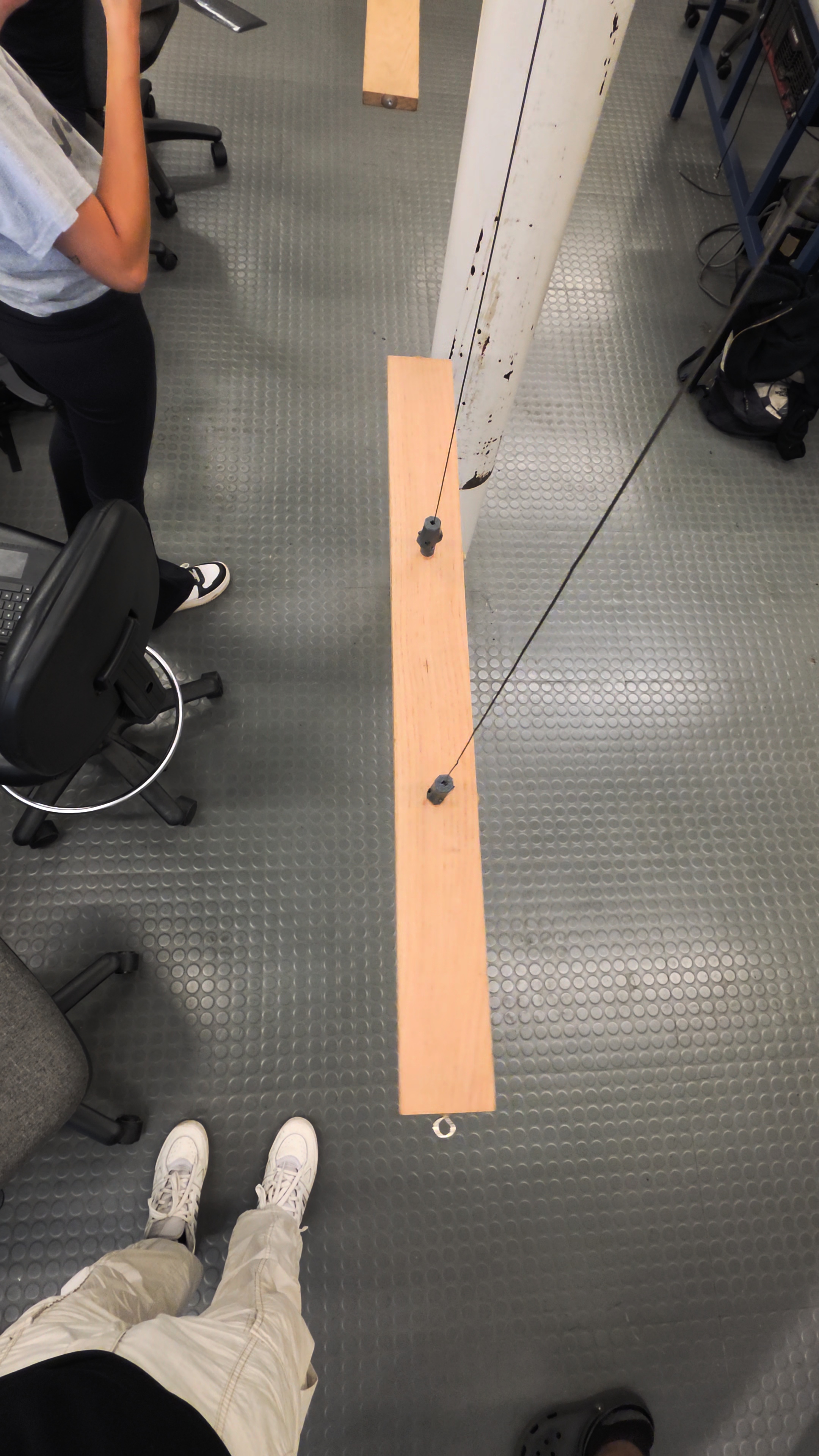
Tested both methods on a wood board whose inertia we could calculate.
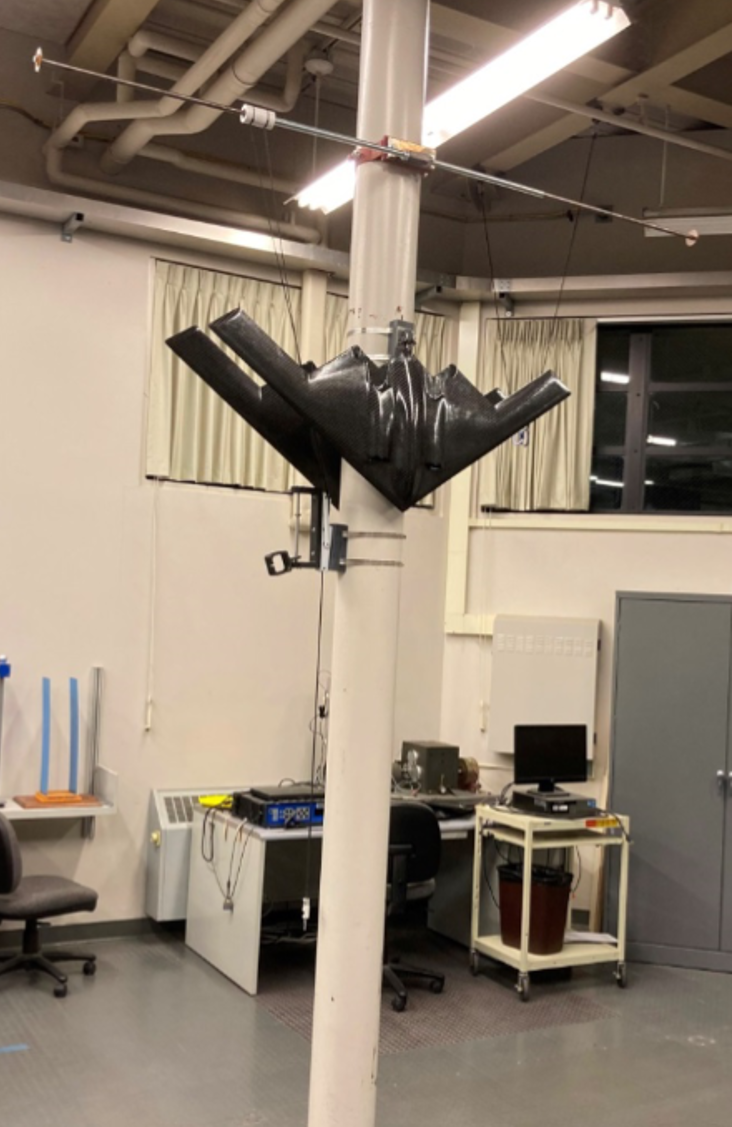
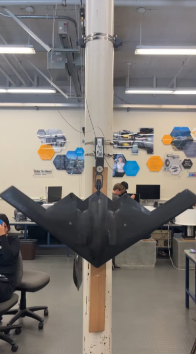
Hung the B-2 from wires and timed its twisting oscillations about each axis.
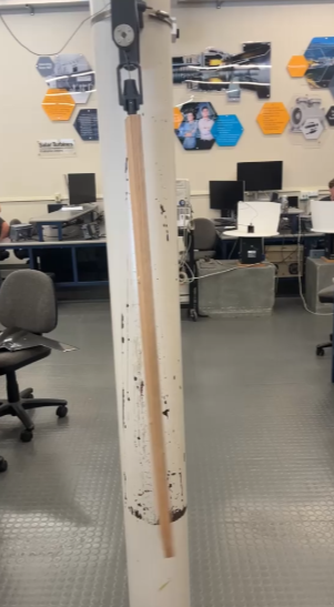
Swung the model as a pendulum for an independent yaw measurement.
Showed a 1% timing error becomes ~10% inertia error, and recommended fixes like a photogate.
Working with Bryan Figueroa, I measured the mass moment of inertia of a B-2 Spirit model about its roll and yaw axes. We first tested both methods on a rectangular wood board with known theoretical inertia, then used the better validated method for the aircraft model.
Known geometry before complex geometry
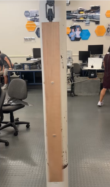
The B-2 model has a complex mass distribution, so no simple geometric equation could provide a trustworthy reference. A uniform wood board supplied that reference. Its dimensions and mass produced theoretical inertia values about the y and z axes that could be compared directly with experiment.
We tested the board with torsional vibration and a physical pendulum. This sequence separated problems in the measurement method from the unknown inertia of the aircraft model.
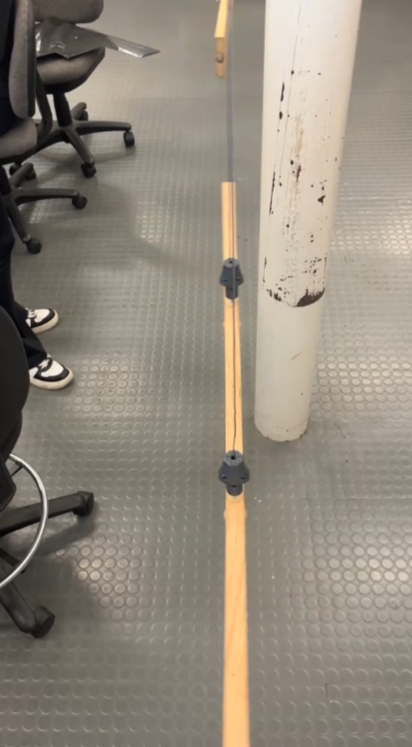
Consistent periods and close agreement with theory
The torsion fixture suspended the test article from wires and allowed small angular oscillations. The measured period, wire spacing, and suspension height produced the experimental inertia.
The wood board result differed from theory by 7.66% about the y axis and only 0.93% about the z axis. That agreement supported using torsional vibration as the primary method for the B-2 model.
| Board axis | Average period | Theoretical inertia | Torsion inertia | Error |
|---|---|---|---|---|
| Y | 4.525 s | 0.20235 kg·m² | 0.18685 kg·m² | 7.66% |
| Z | 4.753 s | 0.20425 kg·m² | 0.20615 kg·m² | 0.93% |
A useful check with higher sensitivity
The pendulum method suspended the test article about an offset pivot. Its inertia calculation used the oscillation period and the measured distance from the pivot to the center of gravity.
The z-axis result stayed within 3.56% of theory, but the y-axis result missed theory by 13.85%. The equation subtracts two similar terms, so small errors in period or center-of-gravity location become much larger errors in the final inertia.
Roll and yaw inertia from measured oscillation
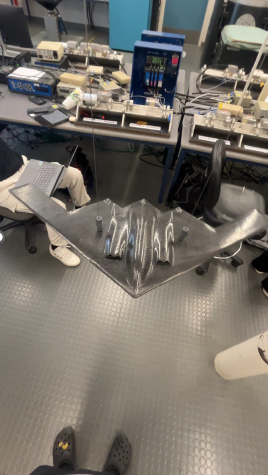
The validated torsion method gave a roll inertia of 0.05476 kg·m² and a yaw inertia of 0.09325 kg·m². The larger yaw value matched the expected behavior of a wide, flat body with more mass distributed away from the vertical axis.
The pendulum test gave a yaw inertia of 0.05894 kg·m², 36.79% below the torsion result. Based on the board validation and the pendulum method’s sensitivity, we selected the torsion value as the more reliable estimate.
Animation by Bryan Figueroa Hernandez, used with permission.
A measured number needs a validated method
The wood board made the experiment defensible. It showed that the torsion setup could reproduce a known inertia before we applied it to the B-2 model.
The disagreement between yaw methods also showed why repeatability alone is not enough. A stable period can still produce a biased result when the equation magnifies small setup errors.